My first caveat is that I’m a building engineer. The layman would be surprised at the differences between the thought processes and building codes that apply to bridges and buildings. However, given the functional intent of this pedestrian bridge, it might is some senses be better treated as a building. To that end, I’ve used the Chicago Building Code (CBC) as a baseline for determining load conditions and general requirements. As we proceed, though, you may find that more elements of common vehicle bridges will find their way into the concept by way of seeking the most efficient forms.
Cantilever bridges were once very common, owing to the ability to construct out from the piers until meeting in the middle. This reduced or eliminated the need for temporary piers or barges located in the deepest part of the body of water below. Employing such a construction method would be advantageous in this example as well, so that the marina below could remain in operation to the fullest extent possible.

I could estimate the weight of the bridge by taking the lumped mass of steel plus another 50% to account for connections, web members and cladding. Depending on the type of façade and the interior build-out, that number could be substantially larger. For the live load, due to pedestrians and amenities, I applied the 100 PSF load stipulated by the CBC for corridors, lobbies and other public space. Notably missing from my quick calculations were allowances for the effects of mother nature. Snow accumulation and lateral wind pressures would place a particularly large demand on any actual structure.
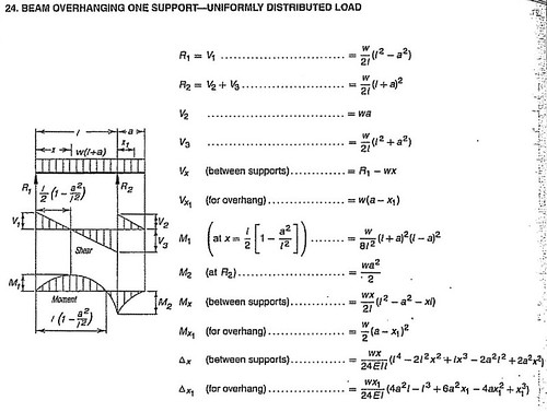
I also experimented with the length of the back-span. Intuitively, I figured that the longer the back-span, the smaller the end displacements. However, since my simple equation assumed the same stiffness throughout the length of the beam, when the back-span length increased too much, it became too flexible to provide a steady prop for the cantilever. This suggests that the architectural concept, which shows a short but deep section behind the forward pier, conceptually meets the structural demand.
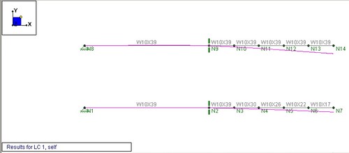
After iterating through my calculations to meet deflection and strength criteria, I arrived at a design that called for about 1200 tons of structural steel. In more graphic terms, the bridge truss superstructure would consist of thirteen 14 in. wide flange beams (I-shaped) each weighing about 120 pounds per foot. Considering the other factors left out of my analysis, this seemed like an expensive brute force way to achieve the design.
These results indicated that the original design had been conceived with sound structural principles in mind. Of course, many issues still remain to be addressed. One such concern is whether the multi-faceted shell will be stable. The jagged exterior form seems to call for some type of internal space frame or self-bracing mechanism to prevent the perimeter from buckling. Surely solutions exist, but a what cost to the overall project.
Without even addressing many additional design considerations, the steel quantities that I had arrived at still seemed heavy. Perhaps more efficiencies could be realized without compromising the architecture. Looking for inspiration, I would turn to other bridge examples. In the form of suspension bridges, I remembered the principles of catenary structures. To be continued in the next post…
How would you have conducted this schematic evaluation? Do you agree with the load applied? Would you have used the full section depth to estimate the building stiffness? What other important considerations were ignored in this evaluation?
![Reblog this post [with Zemanta]](http://img.zemanta.com/reblog_e.png?x-id=24742821-c520-4b18-adf6-73e82a57eca4)
3 comments on "Will a bridge link Northerly Island?"
A space truss is the obvious way to design this structure, given the need to support cladding and resist wind loads as well as to carry the vertical loads. A pure cantilever bridge is not the only option, however: think of the Forth Rail Bridge, or the Simone de Beauvoir footbridge in France, where cantilever arms support a suspended span in the middle.
Dead load deflection is essentially irrelevant: the steelwork can be designed with an upwards precamber so that it will return to its intended position once deflected - this is normal in bridge design of any size.
The fundamental difficulty here is the trend in modern CGI architecture to regard structure as an afterthought rather than a determinant. At 200m span, any engineer should be embarrassed that their structure is having to fit the architect's form, rather than the reverse.
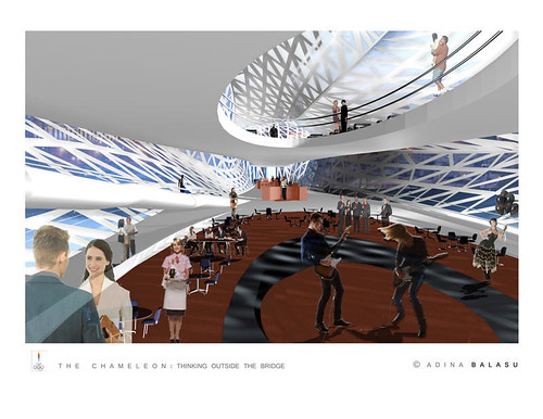
I agree with your point of view. The structure precluded the architecture in this design. My focus was to come up with a prototype for spanning and enclosing and the idea of a 3D Space Frame developed. Architecture was secondary to gain a sense of space. My understading of this structure is that it would stand as two cantilever arms of an arch. I believe without the arched shape the structural connections to the ground would have to be rethought. More drawings of the structure are on my website: www.adinabalasu.com > Portfolio > Innovations > The Chameleon
Thanks for your comments and thanks Ken for this Blog!
Adina
A land forms in full 3D, she rotates and revolves on specially designed Cantilever arms
Post a Comment