


The Chameleon is a design concept for linking Chicago’s Northerly Island to the shore near Soldier field. In the second part of my series exploring the potential structure of this design, I applied basic load and deflection principles to estimate a steel quantity. Unsatisfied with the brute force approach, I explored other structural forms and became intrigued by the concept of the catenary.

A catenary is the theoretical shape that a hanging chain or cable will assume when acted on only by its own weight. Such a member experiences only tension forces and is very efficient for spanning a distance.  The inverse would be the classical arch, a design feature that ideally only experiences compression. Both structural concepts were widely implemented until the advent of steel beams. In fact, the Catalan architect Antoni Gaudi was known to utilize catenary models in his most famous works. A series of strings was used to construct the complex arch and vault system he desired - just upside down. Gaudi realized the relationship between strings in pure tension and stones in pure compression, a law most eloquently described by Newton. “To every action there is an equal and opposite reaction.”
The arc of the catenary is defined by a fairly simple mathematical relationship. y=a*cosh(x/a) The key constant in the equation, “a,” represents a relationship between the tensile force in the member and the applied gravitational force. By tuning the axial stiffness, or resistance to elongation, and strength of the members the arc can be adjusted. Even within fairly rigid confines, such as those set by the need to allow boats to pass beneath the bridge, a satisfactory geometry can be achieved.

Recently building engineers have begun to revisit the potential of catenary action. Many of the most recent reports have dealt with the capacity for floor systems to apply catenary effects to prevent progressive collapse. If properly detailed, the floor beams on several floors can actually form a catenary that will support a column despite the removal of a column support. These recent reports still caution that the method is only effective when large deformations occur and the system has a substantial span to depth ratio. Fortunately, both of these conditions may be permitted in our long span bridge design.
Several bridge forms that utilize this structural technique. Simple rope bridges, like those creaky death traps featured on Indiana Jones, are the most elementary catenary structure. Unlike a conventional suspension bridge, these parabolic structures follow a true catenary curve, because the flexible deck follows the free hang of the cable. The longest such rope bridge, located near Vancouver, is an incredible 450 ft. long. Of course, the problem with these true catenary structures is the bounce and sway experienced by the brave souls that cross them.
 Hybrid applications of the catenary shape have been applied in more static conditions. While the cable of a suspension bridge may initially follow a catenary arc, once the deck cables are attached, the form becomes a parabola carefully computed by the designers. Nor is it essential to use cables to achieve the purpose. Tower Bridge, in London, is known as a suspension bridge, but the “cables” are actually riveted steel plate sections. Therefore, we can assume that a catenary form can be applied to a solid static form.

The major implicit challenges are tuning the member sizes to achieve the final elongated position and constructing given the daily changing member orientations (as construction load is applied). Such a non-linear analysis and sequencing model is beyond the scope of this speculative blog. However, if we overlay a tension catenary (blue) and a compression arch (red) on the elevation of the bridge, we can see potential in the architectural form. Two more parabolic lines (green) appear to close the gaps, facilitating a continuous structure. Even if the intent of the exterior surface is to be undulating and unpredictable, we could envision facet lines that follow the main structural form or find ways to embed that within the structure. I believe this is a concept that brings structural harmony and simplification to a chaotic form that is more visually indicative of the sense of turbulent times.
 Taking the catenary concept one step further, I would further propose that the interior pedestrian paths be supported by the means of one massive catenary bridge. Spanning 600 ft., it would be the longest “rope bridge” in the world. Far from typical, this catenary bridge would be comprised of dual layers with a depth of 16 ft. between. Ramps would connect the two layers and provide exit from the top down to dry land. The original programming called for entertainment and snack bar venues. Providing a stable surface, not wildly influenced by passing pedestrians would be challenging. Perhaps, the catenary pedestrian bridge could be connected to the exterior structure via a system of dampers, to modulate the movement and sway.
Though the initial design suggests that the pedestrian walks be suspended from the super structure, the incorporation of a pedestrian catenary bridge might provide the necessary construction platform to facilitate the building of the shell structure. At times during construction, might the shell actually be suspended from the pedestrian bridge. This might be a significant design consideration that has greater bearing in determining the size of the catenary bridge members than the actual person load.
Though this analysis has been brief, I hope it has accurately represented the thought process of an engineer presented with a design challenge. Use of catenary and arch forms is far from new technology, but they may be appropriate for this project. Even within an apparently static form, there might be potential to implement a bridge form known in the popular mindset as awkwardly unstable. From a structural dreamer’s standpoint the irony of the design is quite satisfying. Delivering a record setting structure goes even further in achieving the goal of a landmark bridge.
What other examples of catenary bridges are out there? Does the catenary concept have merit? Do you think the pedestrian platform would be steady enough to be comfortable? How might contractors cope with the gradual change in shape that will occur in the structure throughout construction? Comment below.
![Reblog this post [with Zemanta]](https://lh3.googleusercontent.com/blogger_img_proxy/AEn0k_v8JyfyPSS_eBdOQX-g6HmhB2F7OfaK15JdwQFXIAdm-Wwb-FxGma6X2aHlzlmyBxFSyQWIS6dnc2WNCVTvK_W93Mxf78U5bjKwTlvm5pFsvNa9Vr9vEQhcU6W4VCmJQdY1rzr7B3OVjOaaQEcO6bSQ=s0-d)
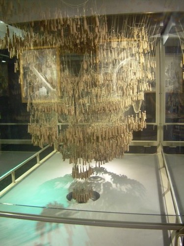 The inverse would be the classical arch, a design feature that ideally only experiences compression. Both structural concepts were widely implemented until the advent of steel beams. In fact, the Catalan architect Antoni Gaudi was known to utilize catenary models in his most famous works. A series of strings was used to construct the complex arch and vault system he desired - just upside down. Gaudi realized the relationship between strings in pure tension and stones in pure compression, a law most eloquently described by Newton. “To every action there is an equal and opposite reaction.”
The arc of the catenary is defined by a fairly simple mathematical relationship. y=a*cosh(x/a) The key constant in the equation, “a,” represents a relationship between the tensile force in the member and the applied gravitational force. By tuning the axial stiffness, or resistance to elongation, and strength of the members the arc can be adjusted. Even within fairly rigid confines, such as those set by the need to allow boats to pass beneath the bridge, a satisfactory geometry can be achieved.
Several bridge forms that utilize this structural technique. Simple rope bridges, like those creaky death traps featured on Indiana Jones, are the most elementary catenary structure. Unlike a conventional suspension bridge, these parabolic structures follow a true catenary curve, because the flexible deck follows the free hang of the cable. The longest such rope bridge, located near Vancouver, is an incredible 450 ft. long. Of course, the problem with these true catenary structures is the bounce and sway experienced by the brave souls that cross them.
 Hybrid applications of the catenary shape have been applied in more static conditions. While the cable of a suspension bridge may initially follow a catenary arc, once the deck cables are attached, the form becomes a parabola carefully computed by the designers. Nor is it essential to use cables to achieve the purpose. Tower Bridge, in London, is known as a suspension bridge, but the “cables” are actually riveted steel plate sections. Therefore, we can assume that a catenary form can be applied to a solid static form.
 Taking the catenary concept one step further, I would further propose that the interior pedestrian paths be supported by the means of one massive catenary bridge. Spanning 600 ft., it would be the longest “rope bridge” in the world. Far from typical, this catenary bridge would be comprised of dual layers with a depth of 16 ft. between. Ramps would connect the two layers and provide exit from the top down to dry land. The original programming called for entertainment and snack bar venues. Providing a stable surface, not wildly influenced by passing pedestrians would be challenging. Perhaps, the catenary pedestrian bridge could be connected to the exterior structure via a system of dampers, to modulate the movement and sway.
Though the initial design suggests that the pedestrian walks be suspended from the super structure, the incorporation of a pedestrian catenary bridge might provide the necessary construction platform to facilitate the building of the shell structure. At times during construction, might the shell actually be suspended from the pedestrian bridge. This might be a significant design consideration that has greater bearing in determining the size of the catenary bridge members than the actual person load.
Though this analysis has been brief, I hope it has accurately represented the thought process of an engineer presented with a design challenge. Use of catenary and arch forms is far from new technology, but they may be appropriate for this project. Even within an apparently static form, there might be potential to implement a bridge form known in the popular mindset as awkwardly unstable. From a structural dreamer’s standpoint the irony of the design is quite satisfying. Delivering a record setting structure goes even further in achieving the goal of a landmark bridge.
What other examples of catenary bridges are out there? Does the catenary concept have merit? Do you think the pedestrian platform would be steady enough to be comfortable? How might contractors cope with the gradual change in shape that will occur in the structure throughout construction? Comment below.


![Reblog this post [with Zemanta]](https://lh3.googleusercontent.com/blogger_img_proxy/AEn0k_vlvaLAMNTQwgaAvPR_TCznHqHrZVVADAi_HmHw3u-xPlUM4Cs7hkukI7MjZJgtK-25hpruWuTUbgL5UhxiapEs6EP9xz54B0IYnznpxKUZWE_al4J_VnrZX9ZWK10pL3GUFBHbo27SWyNDgYiNIWA=s0-d)


![Reblog this post [with Zemanta]](https://lh3.googleusercontent.com/blogger_img_proxy/AEn0k_u00yQOrquDQxXNjoQDFbKSvgdGcuA86vc0ptfRFNlulApocmTWaNC5KVz5MKrDwyCwxT_O_A8YX-gZsIVtS-7_dwotHYcLJfJu6KXO_iQPoG0S9043m-cBeh1xt0copiUqgJUr_q9bBJUJa9huF-c=s0-d)


![Reblog this post [with Zemanta]](https://lh3.googleusercontent.com/blogger_img_proxy/AEn0k_tFYgWDQObhc4WDuIRqaca0GvCQpXwPpcStpoWwXhoXbas85i4defHKx4LM48xYuQ8kWKphKm6H00_1tvobHoHLuwNBvE4ChOpannF1kNFNmroxDT9s53YcrMbwwu52rIF0dvdSha5yyiiihMpbE7mF=s0-d)
![Reblog this post [with Zemanta]](https://lh3.googleusercontent.com/blogger_img_proxy/AEn0k_tCRfG9TU0DnI29Zz0-FWIQa3NVW7zapX2Pi4SPl6YBlsvbun9ECHvxbp5ICNnzPTgbrIv221SZgN90Ljz1qaorHpV_YbOoH5WLt8Z0MRMjvb3n1CRFF6c0cAldvMayqroxeZ72UKro1ECKNCXmZA_X=s0-d)



![Reblog this post [with Zemanta]](https://lh3.googleusercontent.com/blogger_img_proxy/AEn0k_uX3MbXzJ7benxvm6Sic6LtqLZP6zhO3kPpwsLpcOMm8LjJCzPFPOqp0BIBWIofYxLS4c6Lhpr7IbvCFD-dmId5B1VxfIjHzZ4FbXLvdgIx3eEKUoX9y3B4PUfPUbEFwCKJY8K7fUOQF2kZ8QFsI_PY=s0-d)


![Reblog this post [with Zemanta]](https://lh3.googleusercontent.com/blogger_img_proxy/AEn0k_v09SVsUsWHGm1g7hpIJI0S7wDiog3QBV3Nv14wSMnFh_nRHiKGXymFef2iyH4bAa49LFY-VnmpXHEIOzhz42HrcJrXtPQUDRs2YsHjDU19aFsvikTuNh47fGegjEu2w1rbhAAYd-wgdhGSKbcUIMP1=s0-d)


