...on a parking garage?

The Fairbanks at Cityfront Center in Chicago was built on top of an existing parking garage. In order to support the new football-shaped tower on the center of the garage, a 6-foot deep concrete transfer mat was used to distribute load to the stronger perimeter columns.
Crystal Center

...in crystaline form?

If a tectonic shift sent giant crystals thrusting up through the water’s surface, it might look something like this dramatic arts center prototype by AS+GG. Crystal structures with cantilevers of up to 230 feet are joined at a base beneath the water.
Matrix Gateway Complex

...as a cube?

The Matrix Gateway Complex by AS+GG would be an exception to the rule of monotony in rectilinear buildings. It would provide residents a full 3-D city experience, featuring suspended platforms linking modular housing and community venues.

...like a big "W?"

Walter Towers are Danish architects Bjarke Ingels Group’s latest project in Prague, Czech Republic. Cool design, but will it stand?

Monday, March 8, 2010

The quiet war: architecture and digital technologies

Posted by Will it stand? at 3:31 PM 0 comments
Two weeks ago I attended a lecture/discussion led by Tristan D’Estree Sterk and Douglas Pancoast at the Flatiron Arts Building in Chicago. Both presenters are known for their forward-thinking approach to digital technologies in Architecture.

Tristan founded a small design and technology enterprise called the Office for Robotic Architectural Media & the Bureau for Responsive Architecture (ORAMBRA). We met at the School of the Art Institute of Chicago (SAIC), where we collaborated in teaching a studio on materials and structures. Douglas is now the director of the Architecture and Interior Architecture graduate program at SAIC.

Last fall, Douglas and Tristan welcomed the Association for Computer Aided Design in Architecture (ACADIA) to Chicago for their annual conference. The featured presenters delivered a diverse account of how technology is informing architecture. However, despite the enthusiasm brought by the ACADIA event, some architects continued to question the long-term effects of digital technologies on architecture.


With that history in mind, I entered the recent lecture expecting a demonstration of technological superiority and an argument to adopt digital technologies or get left behind. Instead, the discussion was far more nuanced and philosophical. Instead of merely presenting a few “killer-apps,” Tristan and Douglas attempted to articulate a polemic between new digital technologies and classical design theory. The discussion that followed was intellectual, and to be honest, I had to look up some works, like polemic, when I got home.


Polemic: a controversial argument, as one against some opinion, doctrine, etc.

After leaving the discussion I continued to ponder some of the points that were raised. The following are my perceptions on two topics, as inspired by the talk.

During the presentation, Tristan recalled another architects observation that Western (particularly Christian) culture establishes itself in competition with/ or supremacy over the environment. Many other cultures revere nature or worship the sustaining elements. Christianity, from the earliest chapters of Genesis, places mankind above nature. This line of thought is provocative and largely subconscious but not trivial when it comes to reconciling history, sustainability and technology.

For example, many new analytical procedures have been developed to model efficient heat and light distribution in buildings. However, skeptics refer back to old standards for sizing air conditioners and illuminating rooms. They say that any other approach will be uncomfortable and more expensive. As we enter a new age in design that seeks to be more sustainable, architects must overcome skeptics and re-shape the culture to accept greener norms.

Another healthy discussion focused on the adaptability of buildings as machines for living. An attendee pointed out that the Flatiron Arts building (that the lecture was held at) provided an example of how adaptable traditional design is to new uses. The building began as a warehouse, then was utilized for office space and now houses an eclectic group of art studios. Over time, space has been partitioned into rooms of odd shapes and crooked hallways. Yet, the inefficiency in the layout is recognized as a charming feature of the space, ideally suited for its current residents.

Would new ‘super-buildings’ serve such a diversity of purpose over time? A building uniquely suited for one particular client, may not over time maintain its relevance. Could the Bilbao Guggenheim ever be re-purposed for anything other than a museum? Have some architects over-utilized computer modeling to generate complex forms simply for the sake of looking modern?

Before wholly embracing the digital revolution, perhaps it is worthwhile to ponder the reasons for doing so. I enjoyed the opportunity presented by Tristan and Douglas’ to consider the technological revolution occurring in architecture today.

Saturday, February 6, 2010

Achitects & Beyond

Posted by Will it stand? at 11:18 AM 0 comments
Last Thursday I attended the Architects & Beyond lecture sponsored by the Chicago Young Architects Forum. The event was held at HOKs office in the South Loop. It was marketed as an evening of learning and networking. Four presenters spoke from their personal experiences of setting up new businesses. Three had left safe careers as building architects to follow their passions in non-traditional design arenas.
  • The first presenter set the theme: architects and engineers are uniquely suited with skills that help us solve problems AND these skills need not be limited to building design. Her business was to help other entrepreneurs design a business plan to succeed in the market. She emphasized that your compensation when starting out is 50% financial, 50% experience and feedback. http://www.tillcreative.com/
  • Nathan Benjamin from Planet Reuse was up next. He described his businesses niche in linking stockpiles of re-usable building demolition materials with builders and specifiers. PlanetReuse has evolved into a consulting and brokering company focused on providing the insight, experience and materials its clients need. With a well-defined and efficient process, PlanetReuse expertly matches materials with designers, builders and owners to save projects money, serve LEED efforts and sustain the planet. http://planetreuse.com/
  • A third speaker told of her unlikely transition from architecture to the world of fashion. Mohop shoes, so named for the designers last name, are now among the most fashionable green products on the market. It turns out that Rhino can be used equally well to design a futuristic building as a comfortable sole. Just add a block of carefully selected timber and a CNC end-mill and voila! http://www.mohop.com/

The over-riding lesson is that architects AND engineers have the toolset to take on any number of design challenges, beyond buildings.

While many in attendance were a bit surprised to see an engineer at an AIA event, I was repeatedly encouraged to continue coming. They had lots of questions and wanted to know how to encourage more participation by engineers. I promised that I would do my part. So if youre an engineer tired of hearing presentations about the latest in advanced non-linear response of pre-tensioned members, consider attending some AIA YAF events.
Reblog this post [with Zemanta]

Sunday, January 3, 2010

Will an unreinf. conc. dome stand?

Posted by Will it stand? at 7:43 PM 1 comments
Few 1800-year-olds look so good. From within the rotunda of the Pantheon, you could be excused for thinking that the church was constructed just recently. Among all the remaining Roman sites of the Mediterranean, the basilica is probably the most well preserved. Two features contributed greatly to the preservation: its constant use as a place of worship and the incredible concrete enclosure that protects the interior from the elements.

Piazza dei Rotonda

Constructed in 126 A.D., the Pantheon very likely represents the height of Roman structural engineering achievement. In fact, the 142 ft. diameter cupola is still the largest unreinforced concrete dome in the world. That record is in no jeopardy of being broken, as no modern building code would permit such a structure without the use of at least a minimum of steel reinforcing. And yet the Pantheon stands today without any significant reinforcing to alter the original engineers' design intent.

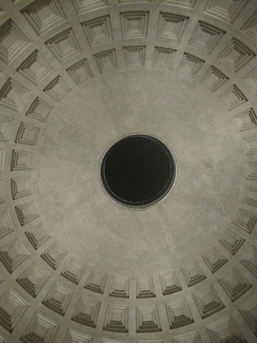
Ancient engineers and architects found a synergy in form that provides a visual experience while enabling the structure to function. Weight was judiciously removed from the roof structure by including a 30 ft. diameter oculus and coffered interior surface. The oculus is simply a large hole in the ceiling that admits the only natural light into the space. Some might also interpret the opening as a spiritual window to the world of the gods. The coffered sides of the dome provide a waffle-shaped pattern that draws attention upward. These two elements give the only outwardly apparent visual clues to the means of structural support.

Several recent investigations have been undertaken to answer the mystery of the structure. The most frequent citation found on online accounts of the Pantheon follows: Mark, R.; Hutchinson, P. (1986), "On the structure of the Pantheon", Art Bulletin 68: 24–34. A nice online summary of those findings is presented by David Moore, P.E. at RomanConcrete.com. Some of the grandstanding is a bit unwarranted, but it is definitely easy to get carries away when describing the achievement of the Roman Engineers.

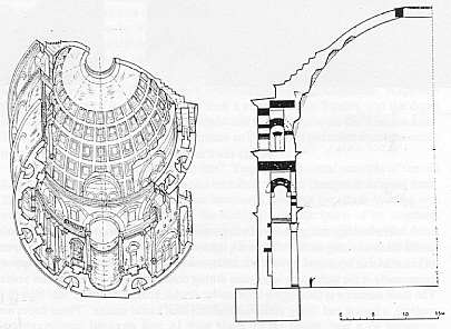
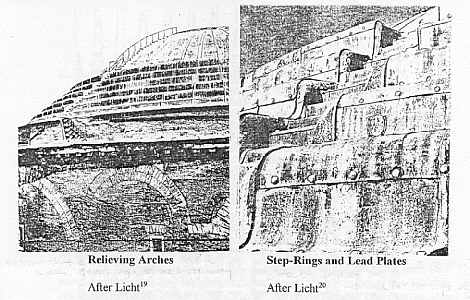
To start with, the original designers were accustomed to super-sized structures. And for all the delicacy portrayed within the Pantheon interior, the first rule of the construction is to build it big. The strip foundation on which the curved building rests is about 34 ft. wide. The wall which supports the dome is about 20 ft. thick. However, perhaps to reduce weight or provide behind the scenes storage space, 8 large niches were created within the otherwise solid wall. As usual, arches are used to great effect to relieve distribute load to piers, thus permitting the openings. This great mass of wall was necessary to provide adequate resistance to the inevitable outward thrust of the dome. No buttresses or perpendicular supporting structures were employed, as was common in later medieval structures.

The dome itself is nearly 20 ft. thick at its base and tapers to just 5 ft. thick at the oculus. A number of techniques were used to achieve the full span. First, a series of seven concentric rings of decreasing size were constructed one on top of the other, like stacking incrementally smaller metal washers. Other authors have suggested that this form is likely borrowed from the very early structural development of the corbeled arch - where a series of stones are stacked, with each cantilevering slightly past the previous. Using this technique, it's possible that the first stages of the dome were constructed without shoring down to the floor.

Beyond the stepped region, the shell becomes a smooth continuous surface. This part of the dome, in addition to the visible interior coffers, was likely cast on formwork supported from below. At the ring of the oculus, the building materials change again. Here a combination of tile and metal plates provide the compression ring that resolves all of the forces acting at the apex of the dome.
The Roman engineers impressively used the materials and methods available to them for maximum structural efficiency. They even created special light-weight concrete to reduce the overall weight of the dome. The 85 lb/ft3 (PCF) mix used at the top of the dome is approximately 40% lighter than today's normal weight concrete. It's even lighter than most conventionally available lightweight concrete. Despite the selection of lightweight aggregates, the engineers still achieved a compressive strength near 3000 lb/in2 (PSI), very near modern expectations for standard strength concrete. It's also important to point out that the Pozzolan binder used by the Romans differs quite a bit from the Portland Cement we use today (which requires a very high energy industrial process).

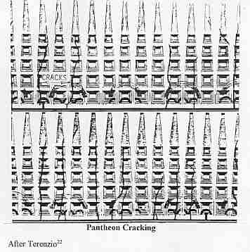
Despite their best efforts, cracks have been witnessed in the dome. The papers I reference above go into detail about their possible origins. They tend to equate the problem as one of excessive tensile hoop stresses near the base of the dome. Like a simple arch, domes also convert vertical forces into horizontal pressure. I prefer to think of the cracking in terms of the small displacement probably occurring at the top of the supporting wall. Stone and concrete, we all know is not a flexible material.

The obvious solution to the problem would be to wrap the base of the dome with some form of tension ring, essentially preventing it from spreading further. However, experts again disagree about when the cracks first appeared. It's possible that they formed immediately after construction, and the dome has stood for over 18 centuries since. It's even possible that the ancient designers were aware of this phenomenon but anticipated it and compensated in the early construction phases.

Barring a catastrophic seismic event, raging fire or destructive conflict, the Roman Pantheon seems to be in shape to survive many more centuries. It is a credit to the initial work of the designers to plan such a robust and awe inspiring building that future generations would have such keen interest in maintenance and preservation. The structural elegance of the rotunda will be an inspiration to engineers for many generations to come.
Do you think that the Pantheon should be reinforced to withstand possible seismic events, or should the original design integrity be maintained? Are modern building codes overly prescriptive, effectively stifiling innovation like that used at the Pantheon? Should naturally occurring Pozzolan binders used more often in modern building construction. Add your comments below.
Reblog this post [with Zemanta]

Wednesday, December 23, 2009

Will smart balloons change design?

Posted by Will it stand? at 12:46 PM 0 comments
At the 2009 ACADIA (Assoc. for CAD In Architecture) conference, I was blown away by all the radical design ideas brought forth. Of them, the most intriguing ideas imagined how new technologies could be used to create responsive structures - buildings that could change shape and function in reaction to external stimuli. Ideas like this are more familiar in the robotics field, but it turns out that simple mechanisms can be utilized to bring our buildings alive.

Mehran Gharleghi and his colleagues at Studio Integrate in London have been exploring the field of responsive structures. Their motivation was to apply simple light weight technologies to provide naturally ventilated and cooled spaces in hot sunny locations. The following is a short description of their research on an Adaptive Pneus in their own words:

image013

"This research focuses on the performative capacities of a pneumatic material system in regard to the specific environmental conditions. It explores a new approach that integrates form generation, material behavior and capacity, manufacturing, and assembly to deliver a modulated environment suitable for occupation.

The focus of the design process and research was the use of Adaptation as a mechanism to modulate environmental performance. Here, adaptability relates to the responsive action that affects the performance of the whole building and, therefore, holds a much closer relationship to the biological and natural ideas of responsiveness.

image011

Location of the sun during the day acts as a trigger to adapt the system, allowing the system to augment passively the environmental conditions. Detection and reaction are embedded in each cell, and responses take place locally and independently. These responses at the regional and global scales allow for the distribution of intelligence across the whole system."
Reblog this post [with Zemanta]

Wednesday, December 9, 2009

Will a catenary span 600 ft?

Posted by Will it stand? at 8:23 AM 3 comments
The Chameleon is a design concept for linking Chicago’s Northerly Island to the shore near Soldier field. In the second part of my series exploring the potential structure of this design, I applied basic load and deflection principles to estimate a steel quantity. Unsatisfied with the brute force approach, I explored other structural forms and became intrigued by the concept of the catenary.

Fireworks
A catenary is the theoretical shape that a hanging chain or cable will assume when acted on only by its own weight. Such a member experiences only tension forces and is very efficient for spanning a distance. The inverse would be the classical arch, a design feature that ideally only experiences compression. Both structural concepts were widely implemented until the advent of steel beams. In fact, the Catalan architect Antoni Gaudi was known to utilize catenary models in his most famous works. A series of strings was used to construct the complex arch and vault system he desired - just upside down. Gaudi realized the relationship between strings in pure tension and stones in pure compression, a law most eloquently described by Newton. “To every action there is an equal and opposite reaction.”

The arc of the catenary is defined by a fairly simple mathematical relationship. y=a*cosh(x/a) The key constant in the equation, “a,” represents a relationship between the tensile force in the member and the applied gravitational force. By tuning the axial stiffness, or resistance to elongation, and strength of the members the arc can be adjusted. Even within fairly rigid confines, such as those set by the need to allow boats to pass beneath the bridge, a satisfactory geometry can be achieved.

Catenary Beams
Recently building engineers have begun to revisit the potential of catenary action. Many of the most recent reports have dealt with the capacity for floor systems to apply catenary effects to prevent progressive collapse. If properly detailed, the floor beams on several floors can actually form a catenary that will support a column despite the removal of a column support. These recent reports still caution that the method is only effective when large deformations occur and the system has a substantial span to depth ratio. Fortunately, both of these conditions may be permitted in our long span bridge design.

Several bridge forms that utilize this structural technique. Simple rope bridges, like those creaky death traps featured on Indiana Jones, are the most elementary catenary structure. Unlike a conventional suspension bridge, these parabolic structures follow a true catenary curve, because the flexible deck follows the free hang of the cable. The longest such rope bridge, located near Vancouver, is an incredible 450 ft. long. Of course, the problem with these true catenary structures is the bounce and sway experienced by the brave souls that cross them.

Hybrid applications of the catenary shape have been applied in more static conditions. While the cable of a suspension bridge may initially follow a catenary arc, once the deck cables are attached, the form becomes a parabola carefully computed by the designers. Nor is it essential to use cables to achieve the purpose. Tower Bridge, in London, is known as a suspension bridge, but the “cables” are actually riveted steel plate sections. Therefore, we can assume that a catenary form can be applied to a solid static form.

Trace_Chamelion
The major implicit challenges are tuning the member sizes to achieve the final elongated position and constructing given the daily changing member orientations (as construction load is applied). Such a non-linear analysis and sequencing model is beyond the scope of this speculative blog. However, if we overlay a tension catenary (blue) and a compression arch (red) on the elevation of the bridge, we can see potential in the architectural form. Two more parabolic lines (green) appear to close the gaps, facilitating a continuous structure. Even if the intent of the exterior surface is to be undulating and unpredictable, we could envision facet lines that follow the main structural form or find ways to embed that within the structure. I believe this is a concept that brings structural harmony and simplification to a chaotic form that is more visually indicative of the sense of turbulent times.

Taking the catenary concept one step further, I would further propose that the interior pedestrian paths be supported by the means of one massive catenary bridge. Spanning 600 ft., it would be the longest “rope bridge” in the world. Far from typical, this catenary bridge would be comprised of dual layers with a depth of 16 ft. between. Ramps would connect the two layers and provide exit from the top down to dry land. The original programming called for entertainment and snack bar venues. Providing a stable surface, not wildly influenced by passing pedestrians would be challenging. Perhaps, the catenary pedestrian bridge could be connected to the exterior structure via a system of dampers, to modulate the movement and sway.

Though the initial design suggests that the pedestrian walks be suspended from the super structure, the incorporation of a pedestrian catenary bridge might provide the necessary construction platform to facilitate the building of the shell structure. At times during construction, might the shell actually be suspended from the pedestrian bridge. This might be a significant design consideration that has greater bearing in determining the size of the catenary bridge members than the actual person load.

Though this analysis has been brief, I hope it has accurately represented the thought process of an engineer presented with a design challenge. Use of catenary and arch forms is far from new technology, but they may be appropriate for this project. Even within an apparently static form, there might be potential to implement a bridge form known in the popular mindset as awkwardly unstable. From a structural dreamer’s standpoint the irony of the design is quite satisfying. Delivering a record setting structure goes even further in achieving the goal of a landmark bridge.

What other examples of catenary bridges are out there? Does the catenary concept have merit? Do you think the pedestrian platform would be steady enough to be comfortable? How might contractors cope with the gradual change in shape that will occur in the structure throughout construction? Comment below.
Reblog this post [with Zemanta]

Will a bridge link Northerly Island?

Posted by Will it stand? at 8:22 AM 3 comments
The Chameleon pedestrian bridge would link Soldier Field to Northery Island. But, will it stand? In this blog, I will apply basic structural principles and equations to estimate the material requirements of such a bridge. To the greatest extent possible, I have tried to remain true to the original design intent, but early schematic evaluations require lots of approximation.

My first caveat is that I’m a building engineer. The layman would be surprised at the differences between the thought processes and building codes that apply to bridges and buildings. However, given the functional intent of this pedestrian bridge, it might is some senses be better treated as a building. To that end, I’ve used the Chicago Building Code (CBC) as a baseline for determining load conditions and general requirements. As we proceed, though, you may find that more elements of common vehicle bridges will find their way into the concept by way of seeking the most efficient forms.

The Bridge Experience
As a building engineer, my first inclination was to evaluate the bridge concept as a beam. In the classic, simply supported beam, the greatest bulk of the structure would necessarily need to be located in the center of the span. However, the architectural intent is to minimize the mass of the structure where it most influences the efficiency of the design. That runs counter to the simple approach. Instead, I thought of the bridge as a system of two cantilevering beams. This type of layout places the greatest cross-section size over the abutments.

Cantilever bridges were once very common, owing to the ability to construct out from the piers until meeting in the middle. This reduced or eliminated the need for temporary piers or barges located in the deepest part of the body of water below. Employing such a construction method would be advantageous in this example as well, so that the marina below could remain in operation to the fullest extent possible.

Interior Perspective
Before I could run some preliminary numbers, I needed to make several estimates about the size and scope of the project. From Google maps, I estimated a free span of 600 ft. Taking all of the abutment requirements into account the real span might be a fair distance larger, but this estimate provides a baseline for exploring the concepts. Secondly, I estimated from the architectural sections, the dimensions of the superstructure. The platforms looked to be about 25 ft wide. The total height might be 45 ft. at the maximum depth. Since the exterior shape was to be comprised of many jagged surfaces, I applied a 33% reduction of the height to approximate the relative location of the main structural elements, treated as two lumps of steel - one representing the top chord of a truss, and the other the bottom chord.

I could estimate the weight of the bridge by taking the lumped mass of steel plus another 50% to account for connections, web members and cladding. Depending on the type of façade and the interior build-out, that number could be substantially larger. For the live load, due to pedestrians and amenities, I applied the 100 PSF load stipulated by the CBC for corridors, lobbies and other public space. Notably missing from my quick calculations were allowances for the effects of mother nature. Snow accumulation and lateral wind pressures would place a particularly large demand on any actual structure.

Cantilever Beam Equations
Nevertheless, I proceeded with a basic cantilever model. With the inputs described above, I was able to use pre-derived equations (taken from the AISC Steel Manual) to estimate the deflection of the beam at it’s cantilevered end and the amount of moment accumulated above the piers. As expected for such a long span, the deflections were large. Use of the spreadsheet allowed me to incrementally increase the amount of structural steel until arriving at quantity that seemed to meet the criteria. Again using my building background, I sought a deflection of no more than the length of the span divided by 360 (an arbitrary, but typically justifiable criteria). A deflection due to live loads up to 20 in. would be acceptable.

I also experimented with the length of the back-span. Intuitively, I figured that the longer the back-span, the smaller the end displacements. However, since my simple equation assumed the same stiffness throughout the length of the beam, when the back-span length increased too much, it became too flexible to provide a steady prop for the cantilever. This suggests that the architectural concept, which shows a short but deep section behind the forward pier, conceptually meets the structural demand.

After iterating through my calculations to meet deflection and strength criteria, I arrived at a design that called for about 1200 tons of structural steel. In more graphic terms, the bridge truss superstructure would consist of thirteen 14 in. wide flange beams (I-shaped) each weighing about 120 pounds per foot. Considering the other factors left out of my analysis, this seemed like an expensive brute force way to achieve the design.

Cantilever Model
I thought back to the original intent to minimize structural mass where not required by strength demands. The simple model assumed that the entire length of the bridge consisted of the same size section. However, because we chose a cantilevered design, the forces in the members would decrease as we approached the end of the cantilever. The structural shape could also taper with that demand. I used RISA 2D, a simple finite element analysis program, to compare the effect of tapered versus constant sections. In the tapered model, I reduced the weight of the section by 60% from the pier to the free end. As a baseline to see if I was still meeting the strength and stiffness minimums, I computed the deflection due to a constant live load first. The results showed an almost negligible difference. The effect on the dead load deflection, however, was a significant 50% reduction.

These results indicated that the original design had been conceived with sound structural principles in mind. Of course, many issues still remain to be addressed. One such concern is whether the multi-faceted shell will be stable. The jagged exterior form seems to call for some type of internal space frame or self-bracing mechanism to prevent the perimeter from buckling. Surely solutions exist, but a what cost to the overall project.

Without even addressing many additional design considerations, the steel quantities that I had arrived at still seemed heavy. Perhaps more efficiencies could be realized without compromising the architecture. Looking for inspiration, I would turn to other bridge examples. In the form of suspension bridges, I remembered the principles of catenary structures. To be continued in the next post…

How would you have conducted this schematic evaluation? Do you agree with the load applied? Would you have used the full section depth to estimate the building stiffness? What other important considerations were ignored in this evaluation?
Reblog this post [with Zemanta]

Will new faces deliver landmarks?

Posted by Will it stand? at 8:20 AM 0 comments
Early in 2009, Chicago’s architecture community was a buzz about the opportunity to design spaces for the 2016 Olympics. They looked to showcase the city’s rich architectural history and implement new modern forms being explored by a new generation of architects. Adina Balasu was one such enterprising designer completing her graduate degree. As part of her studies, she devised a landmark bridge to allow pedestrians access Olympic venues on Northerly Island, just across the marina from Soldier Field.

Night View
The concept, christened Chameleon, was to create a functional bridge that would be a destination in itself. Two levels of walkway would be suspended within a futuristic space frame shell. The large interior space might also be used as a multi-purpose venue for entertainment, retail and relaxation. After the Olympics left, the structure would be a necessary link to further the planned development of the little-used island park. An inspirational form and engineering feat, visitors would make a visit to the Chameleon part of their itinerary, expanding the traditional Chicago tourist district several blocks south.

I was introduced to the project at a meeting of the AIA Young Architects Forum. Following Ms. Balasu’s presentation, we had the opportunity to discuss the details of the project. I was intrigued by the structural challenge and impressed with her desire to express the structural form in the bridge’s appearance to reflect the technology of the times.

I delayed in my review for several months before picking up the concept with a fresh perspective. Unfortunately, in that time, Chicago was passed over for the Olympic bid. Despite this missed opportunity, I started wondering who deliver the trend-setting designs of the future. The current recession seems to have stalled several major projects, and missing out on the Olympics further deflated the local architecture community. When the economy turns around again, who will be at the forefront. I suspect that many of the innovative architects that I met at the YAF will lead the charge.

Outdoor Show
The Chameleon appeals to me as one of those great next-generation architectural concepts. Over the next few blogs I will outline my thought process and presents some potential strategies for making the Chameleon stand.

What do you think, when will we escape the current economic downturn? Will their be a new generation of architects leading the way at that time? Where should enterprising structural engineers look to network with these future partners? Please comment below.
Reblog this post [with Zemanta]
 

Will It Stand? Copyright 2009 Reflection Designed by Ipiet Templates Image by Tadpole's Notez